Husqvarna LGT2654 Manual: A Comprehensive Guide (Updated 04/21/2026)
Today, April 21st, 2026, embark on a journey with this comprehensive guide, unlocking the full potential of your Husqvarna LGT2654 with its parts diagram.
Welcome to the world of Husqvarna lawn tractors! This manual serves as your dedicated resource for understanding and maintaining your new Husqvarna LGT2654. Designed for both seasoned operators and first-time users, this guide provides detailed instructions, safety precautions, and maintenance schedules to ensure years of reliable performance.

The LGT2654 is a powerful and versatile machine built to tackle a variety of landscaping tasks. This manual will help you maximize its capabilities, from efficient mowing to handling attachments. Please retain this manual for future reference – it’s an invaluable tool for keeping your tractor in optimal condition. Understanding the components and procedures outlined within will contribute to a safe and productive experience.
We encourage you to familiarize yourself with all sections before operating the LGT2654.
Understanding the LGT2654 Model
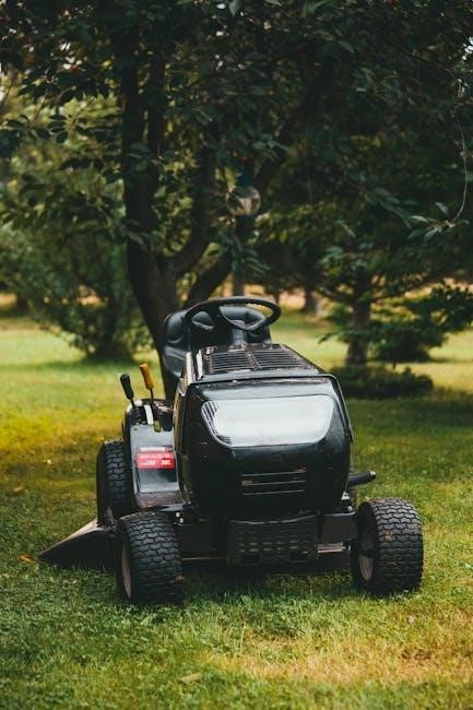
The Husqvarna LGT2654 is a robust lawn tractor engineered for residential and light commercial use. It features a durable steel frame, a powerful engine, and a precision-engineered cutting deck. This model is designed for efficient operation and long-lasting reliability, offering a comfortable experience for the operator.
Key features include hydrostatic transmission for smooth speed control, an ergonomic operator station, and easy access to service points. The LGT2654 is also compatible with a range of attachments, expanding its versatility beyond basic mowing. Refer to the parts diagram throughout this manual to visualize component locations and understand their functions.
Familiarizing yourself with these aspects will enhance your ability to maintain and operate the tractor effectively.

Safety Precautions & Operating Instructions
Prioritize safety! Always read this manual thoroughly before operating the Husqvarna LGT2654, understanding all precautions and operating procedures for safe use.
General Safety Rules
Crucially, always disconnect the spark plug wire before performing any maintenance or adjustments to prevent accidental starting. Never operate the mower if you are tired, ill, or under the influence of drugs or alcohol. Ensure all bystanders, especially children and pets, are a safe distance away during operation.
Always wear appropriate safety gear, including eye protection, sturdy footwear, and hearing protection. Never remove or bypass safety devices. Inspect the mowing area for obstacles that could be thrown by the blade. Be aware of potential hazards like uneven terrain and hidden objects.
Refuel only when the engine is cool and with the mower positioned on a level surface. Avoid creating sparks or open flames near fuel. Report any damaged or malfunctioning parts immediately and do not operate the mower until repairs are completed. Understand the machine’s controls and operation before use.
Pre-Operational Checks
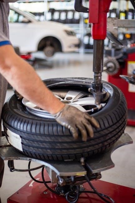
Before each use, meticulously inspect the mower for any loose or damaged parts, paying close attention to blades, belts, and guards. Verify that all nuts and bolts are securely tightened. Check the oil level and add oil if necessary, using the recommended type. Ensure the fuel tank contains sufficient fuel, and inspect for leaks.
Examine the tires for proper inflation and any signs of wear or damage. Confirm the safety interlock switches are functioning correctly. Inspect the deck for obstructions or debris. Test the blade engagement and disengagement mechanisms. Finally, ensure the parking brake is fully engaged before starting the engine.
A thorough pre-operational check minimizes risks and ensures optimal performance. Remember to consult the parts diagram for component locations and identification during inspection.
Starting and Stopping the Engine
To start the engine, ensure the parking brake is engaged and the blades are disengaged. Turn the ignition key to the “ON” position. If the engine is cold, use the choke. Press and hold the safety interlock button while turning the key further to the “START” position. Release the key once the engine starts. Allow the engine to warm up before operating.
To stop the engine, disengage the blades and slowly move the throttle to the “IDLE” position. Turn the ignition key to the “OFF” position. Remove the key to prevent accidental starting. Never abruptly shut off the engine while under load. Always allow the engine to cool down before performing maintenance.
Refer to the parts diagram if you encounter issues with the ignition system.
Mowing Techniques for Optimal Results
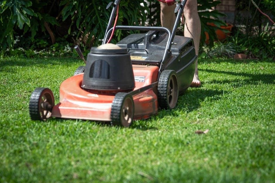
For a pristine lawn, overlap each mowing pass by approximately one-third of the deck width. Maintain a consistent mowing speed to ensure an even cut. Adjust the cutting height based on grass type and desired length – avoid removing more than one-third of the grass blade at a time.
Mow in a different direction each time to prevent grass from leaning. When mowing tall grass, raise the deck height and make multiple passes, lowering the height with each pass. Avoid mowing wet grass, as it can clog the deck and result in an uneven cut. Sharp blades are crucial for a clean cut.
Consult the deck components parts list for blade maintenance.
Maintenance Schedule & Procedures
Regular upkeep ensures peak performance and longevity of your Husqvarna LGT2654. Follow the outlined procedures for optimal operation and reliability.
Regular Maintenance Tasks
Consistent maintenance is crucial for the Husqvarna LGT2654’s reliable operation. Begin with a pre-mowing inspection, checking tire pressure, and ensuring all bolts are tightened securely. After each use, thoroughly clean the mowing deck, removing grass clippings and debris to prevent corrosion and maintain cutting efficiency.
Weekly, inspect the engine oil level and top off as needed, using the manufacturer’s recommended grade. Check the air filter for dirt and debris; cleaning or replacing it ensures optimal engine performance. Lubricate all moving parts, including the steering components and blade engagement levers.

Monthly, inspect the drive belt for wear and tear, and adjust its tension if necessary. A well-maintained machine delivers superior results and extends its lifespan considerably.
Air Filter Maintenance
Maintaining a clean air filter is paramount for optimal engine performance on your Husqvarna LGT2654. A dirty filter restricts airflow, leading to reduced power and increased fuel consumption. Inspect the air filter after every 25 hours of operation, or more frequently in dusty conditions.
To clean a foam filter, wash it in warm, soapy water, rinse thoroughly, and allow it to dry completely before re-oiling with air filter oil. For paper filters, gently tap it to remove loose debris; avoid using compressed air, as it can damage the filter media.
Replace the air filter annually, or sooner if it’s damaged or excessively dirty. A new filter ensures a clean air supply, maximizing engine efficiency and prolonging its life.
Blade Sharpening and Replacement
Sharp blades are crucial for a clean cut and healthy lawn with your Husqvarna LGT2654. Dull blades tear the grass, causing it to brown and become susceptible to disease. Inspect blades regularly for damage – nicks, bends, or excessive wear.
Sharpen blades at least once a season, or more often if you mow frequently or encounter abrasive conditions. Use a file or a blade grinder, ensuring you maintain the original angle. Always balance the blades after sharpening to prevent vibration and uneven cutting.
Replace blades when they are severely damaged or cannot be sharpened effectively. Use only genuine Husqvarna replacement blades, and always follow proper safety procedures during installation.
Engine Oil Change Procedure
Regular oil changes are vital for maintaining the longevity of your Husqvarna LGT2654’s engine. Refer to the ‘Fluid Capacities’ section for the correct oil type and quantity. Always perform oil changes with the engine warm, but not hot, for optimal drainage;
Begin by disconnecting the spark plug wire for safety. Locate the oil drain plug and position a drain pan underneath. Remove the plug and allow the oil to drain completely. Replace the drain plug and tighten securely.
Next, remove the oil filter and lightly lubricate the gasket of the new filter with fresh oil. Install the new filter, tightening it hand-tight plus an additional half turn. Finally, add the correct amount of oil and check the dipstick.
Cooling System Maintenance
Maintaining the cooling system is crucial to prevent overheating and engine damage in your Husqvarna LGT2654. Regularly inspect the radiator and cooling fins for debris, such as grass clippings and dirt, which can restrict airflow.
Carefully clean the radiator and fins using compressed air or a soft brush, directing the airflow outwards. Check the coolant level and top up with the recommended coolant mixture as specified in the ‘Fluid Capacities’ section.

Inspect hoses for cracks, leaks, or swelling, replacing them if necessary. Ensure the fan operates correctly when the engine is running. A properly maintained cooling system ensures optimal engine performance and longevity.
Hydraulic System Maintenance
Proper hydraulic system maintenance is vital for smooth operation of the LGT2654’s lifting and steering functions. Regularly check the hydraulic fluid level using the dipstick, ensuring it’s within the recommended range – refer to ‘Fluid Capacities’ for specifics.
Inspect hoses and connections for leaks or damage, tightening connections as needed and replacing damaged hoses promptly. Change the hydraulic fluid and filter according to the ‘Maintenance Schedule’ to remove contaminants.
Avoid overfilling the hydraulic reservoir, as this can cause system damage. Listen for unusual noises during operation, which may indicate a problem. A well-maintained hydraulic system guarantees efficient and reliable performance.

Troubleshooting Common Issues
Diagnose and resolve frequent problems like starting failures, blade engagement difficulties, hydraulic malfunctions, and electrical system errors with this helpful guide.
Engine Starting Problems
Experiencing difficulty starting your Husqvarna LGT2654? Several factors could be at play. First, verify the fuel level and ensure the fuel shut-off valve is open. A clogged air filter restricts airflow, hindering ignition; inspect and clean or replace it as needed.
Check the spark plug for fouling or damage, replacing it if necessary. Low battery charge can prevent the engine from cranking; charge or replace the battery. Ensure the safety interlock switches (seat switch, blade engagement switch) are functioning correctly. If the engine cranks but doesn’t start, suspect a fuel delivery issue – inspect the fuel lines and carburetor. Finally, consult a qualified technician if problems persist.
Blade Engagement Issues
Trouble engaging the blades on your Husqvarna LGT2654? Begin by confirming the blade engagement lever is fully depressed and locked into position. Inspect the belt connecting the engine to the deck; a worn or broken belt will prevent blade engagement.
Check the belt tension – it should be within the manufacturer’s specifications. Examine the PTO (Power Take-Off) clutch for proper operation; a faulty clutch won’t engage the blades. Verify the deck is free of obstructions, as debris can jam the system. Ensure the safety switches are functioning correctly, preventing operation if bypassed. If issues continue, seek professional assistance for diagnosis and repair.
Hydraulic System Malfunctions
Experiencing issues with the hydraulic system of your Husqvarna LGT2654? First, check the hydraulic fluid level – low fluid is a common cause of malfunctions. Inspect for leaks around hoses, cylinders, and the pump. A clogged hydraulic filter can restrict flow and reduce performance; replace it as needed.
Listen for unusual noises, like whining or hissing, which may indicate a failing pump. Verify the hydraulic lines aren’t kinked or damaged. If steering or lifting functions are sluggish, air may be in the system, requiring bleeding. Consult a qualified technician for complex repairs or if you’re uncomfortable working with the hydraulic system.
Electrical System Problems
Facing electrical issues with your Husqvarna LGT2654? Begin by inspecting the battery connections for corrosion and ensuring they are tight. A blown fuse is a frequent culprit; check the fuse box and replace any damaged fuses with the correct amperage. Test the battery voltage to confirm it’s adequately charged.
Examine the wiring harness for damaged or frayed wires. Check the ignition switch and safety interlocks – a faulty switch can prevent starting. If the lights aren’t working, verify the bulbs and wiring. Consult a qualified technician for diagnosing and repairing complex electrical faults, especially those involving the charging system or engine control unit.

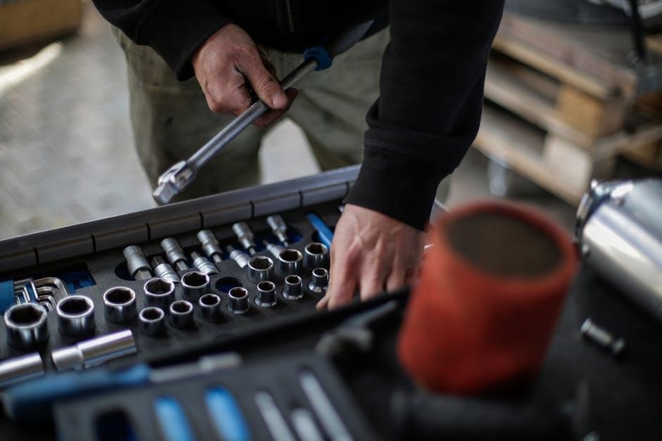
Parts Diagram & Identification
Navigate the detailed diagrams to precisely locate components, ensuring accurate identification for repairs and maintenance of your Husqvarna LGT2654 effectively.
Locating Parts in the Diagram
Understanding the parts diagram is crucial for efficient maintenance and repair of your Husqvarna LGT2654. Each diagram is meticulously organized, showcasing exploded views of various assemblies. Begin by identifying the primary assembly you’re working with – deck, engine, or hydraulic system.
Parts are typically numbered, with a corresponding parts list providing descriptions and part numbers. Pay close attention to the orientation of components as shown in the diagram; this ensures correct installation. Utilize the key or legend to decipher symbols and abbreviations used throughout the diagram.
Zooming in on specific areas can aid in identifying smaller parts. Cross-referencing the diagram with the parts list is essential for accurate part identification. If unsure, consult a qualified technician or Husqvarna dealer for assistance. Proper part identification prevents incorrect replacements and ensures optimal performance.
Deck Components & Parts
The cutting deck is the heart of your LGT2654’s mowing performance. Key components include the deck shell, blade spindle assemblies, blades, and anti-scalp wheels. The deck shell provides structural support and directs airflow for efficient cutting. Blade spindles house the bearings and secure the blades.
Genuine Husqvarna blades are crucial for a clean cut and prolonged deck life. Anti-scalp wheels prevent the deck from digging into uneven terrain. Regularly inspect these parts for wear and damage.
Replacement parts should match the original specifications. The diagram details each component, including bolts, washers, and retaining clips. Proper assembly and torque specifications are vital for safe operation. Always disconnect the spark plug before working on the deck.
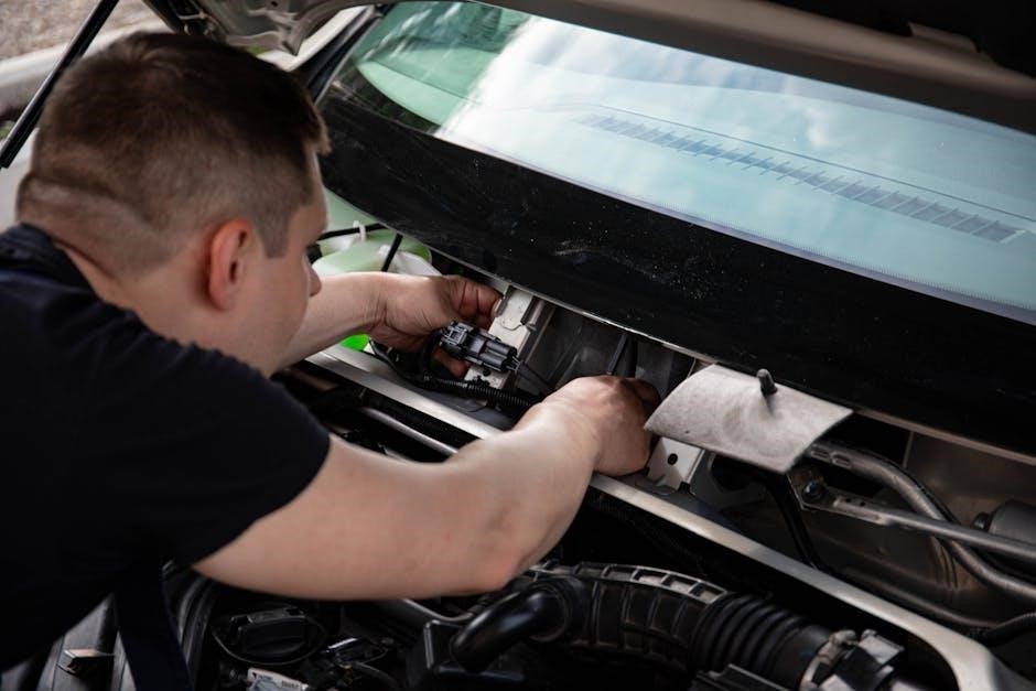
Engine Parts Breakdown
The Husqvarna LGT2654’s engine is a robust power source, requiring occasional maintenance and part replacement. This breakdown details key engine components, including the cylinder, piston, connecting rod, crankshaft, and valve train. The carburetor manages fuel delivery, while the muffler reduces exhaust noise.
Regularly inspect the air filter, spark plug, and fuel lines for wear. Genuine Husqvarna parts ensure optimal performance and longevity. The diagram illustrates each component’s location and part number.
When ordering replacements, verify compatibility with your engine’s serial number. Always consult a qualified technician for complex repairs. Proper torque specifications are critical during reassembly to prevent engine damage.
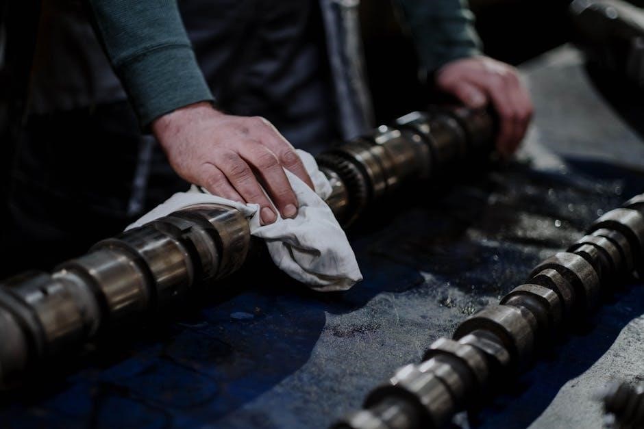
Hydraulic System Parts List
The Husqvarna LGT2654 utilizes a hydraulic system for efficient lifting and steering. This list details essential components, including the hydraulic pump, reservoir, hoses, cylinders, and filters. The pump generates pressure, while the reservoir stores hydraulic fluid.
Hoses and cylinders transmit fluid power to the lift arms and steering mechanism. Regularly inspect hoses for leaks and damage. Genuine Husqvarna hydraulic fluid is crucial for optimal system performance and longevity.
The diagram identifies each part with corresponding numbers for easy ordering. Always disconnect the battery before working on the hydraulic system. Proper maintenance prevents costly repairs and ensures smooth operation.
Technical Specifications
Discover key details about the LGT2654, including engine power, deck size, tire dimensions, and fluid capacities – essential for informed operation and maintenance.
Engine Specifications
The Husqvarna LGT2654 is typically equipped with a Briggs & Stratton Professional Series engine, renowned for its durability and performance. Expect a displacement around 26.5 gross cubic inches, delivering substantial power for demanding tasks.
This engine generally operates on unleaded gasoline with a minimum octane rating of 87. It’s a four-cycle, air-cooled engine, designed for reliable operation. The horsepower rating usually falls between 24-26 HP, providing ample strength for mowing and other lawn care activities.
Furthermore, the engine features a full-pressure lubrication system, enhancing longevity and reducing wear. Understanding these specifications is crucial for selecting the correct oil and maintaining optimal engine health, ensuring years of dependable service from your LGT2654.
Deck Dimensions & Capacity
The Husqvarna LGT2654 boasts a robust 54-inch cutting deck, constructed from heavy-gauge steel for exceptional durability. This substantial width allows for efficient mowing of large properties, reducing overall mowing time significantly. The deck height is adjustable, typically ranging from 1.5 to 4 inches, providing versatility for various grass types and desired cutting heights.
Regarding capacity, the deck is designed to handle a high volume of grass clippings, minimizing clogging and ensuring consistent performance. Its deep design promotes excellent airflow, contributing to a clean and even cut. Proper maintenance, including regular cleaning and blade sharpening, is vital to maximize the deck’s efficiency and lifespan.
Tire Specifications
The Husqvarna LGT2654 is equipped with durable, high-flotation tires designed to provide superior traction and a comfortable ride, even on uneven terrain. Typically, these are 24×12-12 front tires and 20×10-10 rear tires, offering a wide footprint to minimize ground disturbance and prevent scalping.
These tires are specifically chosen for their ability to handle the weight of the tractor and maintain stability during operation. Maintaining proper tire pressure – generally around 18 PSI for the front and 14 PSI for the rear – is crucial for optimal performance and tire longevity. Regular inspection for wear and tear, and timely replacement when needed, ensures continued safe and efficient operation.
Fluid Capacities
Maintaining correct fluid levels is paramount for the longevity and performance of your Husqvarna LGT2654. The engine oil capacity typically requires approximately 1.8 quarts (1.7 liters) of SAE 30 or 10W-30 oil, ensuring optimal lubrication and reducing engine wear. The cooling system, vital for temperature regulation, holds around 1.5 gallons (5.7 liters) of a 50/50 mix of ethylene glycol antifreeze and distilled water.
Furthermore, the hydraulic system demands roughly 3.5 quarts (3.3 liters) of hydraulic tractor fluid, crucial for smooth operation of lifting and steering functions. Always consult the owner’s manual for precise specifications and recommended fluid types to guarantee compatibility and prevent damage.

Warranty Information
Husqvarna stands behind its products! This section details your LGT2654’s warranty coverage and outlines the straightforward process for submitting a warranty claim.
Husqvarna Warranty Coverage
Your Husqvarna LGT2654 is protected by a comprehensive warranty, designed to provide peace of mind and ensure long-term performance. The standard warranty covers defects in materials and workmanship for a specified period, beginning from the original date of purchase.
Specifically, the engine is typically covered for a duration of two years, while the remaining components – including the chassis, deck, and hydraulic system – benefit from a five-year limited warranty. This coverage extends to both residential and commercial use, though commercial applications may have slightly altered terms.
Important Note: Warranty coverage is contingent upon proper maintenance, as outlined in this manual. Failure to adhere to the recommended maintenance schedule may void the warranty. Keep your purchase receipt as proof of date for any claims.
Warranty Claim Process
To initiate a warranty claim for your Husqvarna LGT2654, begin by contacting an authorized Husqvarna dealer. They will serve as your primary point of contact and guide you through the necessary steps. Have your original purchase receipt, model number, and a detailed description of the issue readily available.
The dealer will assess the problem and, if covered under warranty, will either repair the unit or authorize a replacement. Important: Do not attempt to repair the machine yourself, as this may invalidate your warranty.
You may be required to transport the LGT2654 to the dealer’s service center. Husqvarna reserves the right to inspect any claimed defect before approving a warranty claim.