Western Australia Travel Guide Book: An Overview
Discover Western Australia with comprehensive guides from Lonely Planet and Insight Guides, offering itineraries, maps, and local insights for an unforgettable journey.
Western Australia, a land of immense scale and breathtaking diversity, beckons travelers with its untamed wilderness and vibrant city life. From the bustling capital of Perth to the ancient landscapes of the Kimberley, this vast state offers an unparalleled adventure. Travel guides, like those from Lonely Planet and Insight Guides, are essential companions for navigating this remarkable destination.
These resources provide invaluable insights into planning your trip, highlighting key attractions, and uncovering hidden gems. Explore the renowned Margaret River wine region, encounter unique wildlife, and delve into the rich Indigenous culture. Whether you seek outdoor adventures or cultural immersion, Western Australia promises an extraordinary experience, best enjoyed with a well-chosen travel guide in hand.
Planning Your Trip
Effective trip planning for Western Australia relies heavily on utilizing comprehensive travel guides. Resources like Lonely Planet and Insight Guides offer invaluable planning features and expertly crafted itineraries to maximize your experience. Consider the vast distances involved and plan transportation accordingly. Forums, such as those on TripAdvisor, provide access to local expertise and current travel advice.
Before you go, research visa requirements and ensure your travel documents are in order. These guides also detail accommodation options to suit every budget. Don’t forget to explore the “What’s New” sections for the latest updates and discoveries, ensuring a truly unique and informed adventure across this incredible state.

Best Time to Visit Western Australia
Determining the best time to visit Western Australia depends on your desired experiences and regional focus. While a year-round destination, the shoulder seasons – spring (September-November) and autumn (March-May) – generally offer pleasant weather and fewer crowds. The tropical north, including the Kimberley and Coral Coast, is best visited during the dry season (April-October) to avoid monsoonal rains.
Guides highlight regional variations; the Margaret River region is lovely in spring, while Perth enjoys warm summers. Consider peak seasons for potential price increases and booking challenges. Thorough research using travel guides will help align your visit with optimal conditions for specific activities and destinations.
Visa Requirements & Entry
International travelers to Western Australia, and Australia generally, typically require a visa. Visa requirements vary significantly based on your nationality and the purpose of your visit (tourism, work, study). It’s crucial to check the Australian Department of Home Affairs website well in advance of travel to determine the appropriate visa subclass and application process.
Travel guides emphasize the importance of applying for a visa early, as processing times can vary. Electronic Travel Authority (ETA) options are available for citizens of certain countries. Ensure your passport is valid for at least six months beyond your intended stay, and be prepared to provide supporting documentation during entry.
Getting Around Western Australia
Western Australia is vast, making transport planning essential. Renting a car offers the most flexibility, particularly for exploring regions like the Margaret River or the Kimberley. However, distances are significant, and 4WD vehicles are recommended for unsealed roads. Public transport, including buses and trains, connects Perth with major regional centers, but services can be infrequent.
Domestic flights are a practical option for covering large distances quickly. Travel guides suggest considering bus tours for organized exploration of specific areas. Be mindful of fuel availability in remote locations and plan accordingly. Road conditions can vary, so check updates before embarking on long drives.
Destinations & Regions
Explore Perth, the Coral Coast’s Ningaloo Reef, the ancient Kimberley, and the renowned Margaret River wine region – diverse landscapes await discovery!
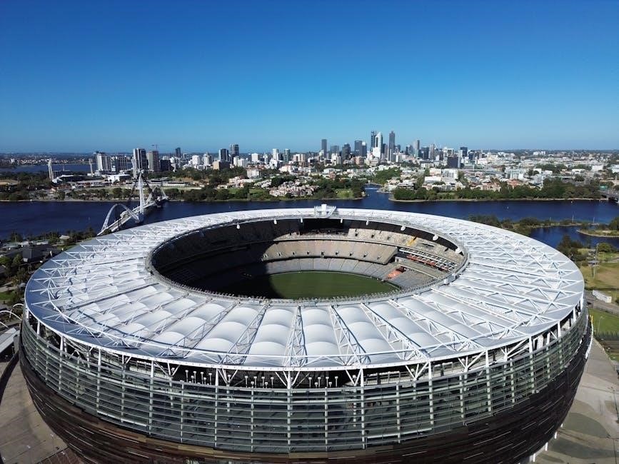
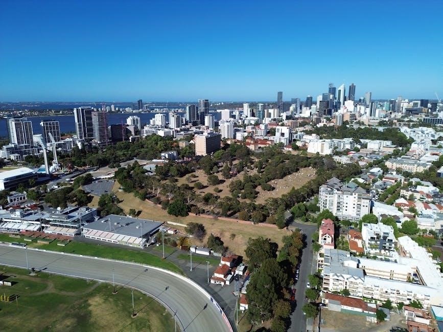
Perth: The Capital City
Perth, the vibrant capital of Western Australia, serves as an excellent starting point for your adventure; Travel guides, like those from Lonely Planet and Insight Guides, highlight Perth’s attractions and cultural scene. Discover inspirational images and expert recommendations to plan your perfect trip.

Explore the city’s unique blend of urban sophistication and natural beauty. These guides offer detailed coverage, including easy-to-use maps and up-to-date information on things to see and do. Uncover local secrets and hidden gems that will enhance your experience. From bustling markets to serene parks, Perth offers something for every traveler, making it a truly memorable destination.
Attractions in Perth
Perth’s attractions are thoroughly detailed in travel guides, ensuring you don’t miss a highlight. Explore Kings Park and Botanic Garden, offering stunning city views and native flora. Discover the vibrant Elizabeth Quay, a modern waterfront precinct with restaurants and bars.
Fremantle, a historic port city, is easily accessible and brimming with maritime history and charming architecture. These guides provide authoritative background information and practical recommendations for exploring these sites. They also suggest itineraries for maximizing your time, including top 10 lists and cross-referenced maps, making Perth’s attractions easily navigable and enjoyable for all visitors.
Perth’s Cultural Scene
Travel guides highlight Perth’s thriving cultural landscape, showcasing its art, history, and Indigenous heritage. Discover the Art Gallery of Western Australia, featuring diverse collections and exhibitions. Explore the Western Australian Museum Boola Bardip, delving into the state’s natural and cultural history.
These resources detail Indigenous art centers and heritage sites, offering insights into Aboriginal culture. They also recommend performances and events, ensuring a rich cultural experience. With up-to-date coverage and local secrets, these guides help you navigate Perth’s cultural scene, uncovering hidden gems and unique experiences for every traveler.
The Southwest: Margaret River & Beyond
Travel guides extensively cover the Margaret River region, famed for its world-class wineries and stunning coastal scenery. Discover top vineyards and cellar doors, alongside recommendations for gourmet food experiences. Explore the region’s beautiful beaches and charming coastal towns, perfect for surfing and relaxation.
These resources offer detailed itineraries for exploring beyond Margaret River, including national parks and natural attractions. They highlight hidden travel gems and local secrets, ensuring an unforgettable journey through Western Australia’s southwest. Expect insightful maps and practical advice for planning the perfect trip.
Margaret River Wine Region
Western Australia travel guides dedicate significant coverage to the Margaret River Wine Region, showcasing its diverse range of wineries. Expect detailed descriptions of cellar doors, offering insights into wine tasting experiences and vineyard tours. Guides highlight premier producers and boutique wineries, catering to all palates.
Beyond wine, these resources detail gourmet food pairings and local culinary delights. Maps pinpoint vineyard locations, while itineraries suggest self-drive routes and organized tours. Discover hidden gems and local secrets within the region, enhancing your wine country adventure.
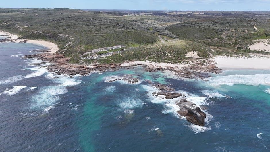
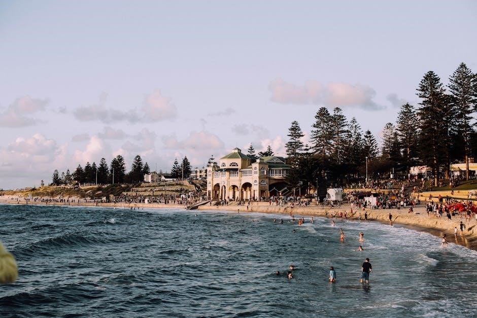
Beaches & Coastal Towns
Western Australia travel guides extensively feature the stunning beaches and charming coastal towns of the Southwest. Expect detailed descriptions of popular surf spots, secluded bays, and pristine stretches of sand. Guides highlight opportunities for swimming, snorkeling, and water sports along the coastline.
Discover picturesque towns like Busselton, Dunsborough, and Yallingup, with recommendations for accommodation, dining, and local attractions. Maps pinpoint beach access points and coastal walking trails, while itineraries suggest scenic drives and day trips. Explore hidden coves and enjoy the relaxed coastal lifestyle.
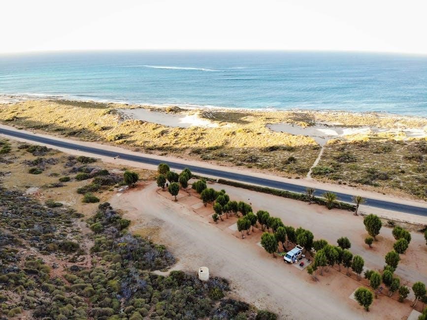
The Coral Coast
Western Australia travel guides dedicate significant coverage to the breathtaking Coral Coast region. Expect detailed information on Ningaloo Reef, a UNESCO World Heritage site, famed for its incredible marine biodiversity and opportunities to swim with whale sharks. Guides outline tour operators and responsible tourism practices.
Discover Monkey Mia, renowned for its daily dolphin interactions, with advice on ethical viewing guidelines. Explore the coastal towns, national parks, and dramatic landscapes. Maps highlight key locations, while itineraries suggest road trip routes and adventure activities along this spectacular coastline.
Ningaloo Reef: Whale Sharks & Marine Life
Travel guides emphasize Ningaloo Reef as a premier destination for encountering whale sharks – the world’s largest fish – offering responsible swim tours. Detailed sections cover the best times to visit for whale shark sightings (typically March to August) and booking reputable operators prioritizing marine conservation.
Beyond whale sharks, guides highlight the reef’s diverse marine life: manta rays, turtles, colorful coral, and numerous fish species. Snorkeling and diving information, including site recommendations and safety advice, are prominent. Expect maps pinpointing key reef locations and details on access points.
Monkey Mia: Dolphin Interactions
Travel resources consistently feature Monkey Mia as a unique location for wild dolphin interactions. Guides detail the daily feeding program, emphasizing responsible tourism practices and the importance of adhering to park regulations to protect the dolphins’ natural behavior.
Information includes arrival times for dolphin encounters, guidelines for respectful observation, and details about the research conducted at Monkey Mia. Beyond dolphins, guides also highlight other wildlife in the area, such as dugongs, turtles, and various bird species. Expect practical advice on accommodation, tours, and accessibility.
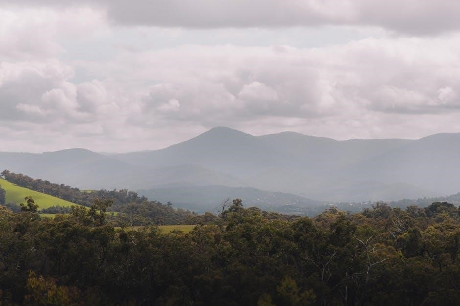
The Kimberley: Ancient Landscapes
Travel guides emphasize the Kimberley region’s raw beauty and vastness, detailing iconic locations like El Questro Wilderness Park and the Bungle Bungle Range (Purnululu National Park). Resources provide practical advice for navigating this remote area, including 4WD requirements, seasonal road closures, and the necessity of pre-booking tours and accommodation.
Information covers hiking trails, gorges, waterfalls, and Aboriginal cultural sites. Guides highlight the region’s unique geological formations and ancient history. Expect details on permits, safety precautions, and responsible travel practices to minimize environmental impact within this pristine wilderness.
El Questro Wilderness Park
Travel guides detail El Questro as a premier Kimberley destination, showcasing its diverse landscapes – from rugged gorges and thermal springs to lush rainforest pockets. Information covers accommodation options, ranging from campsites to the luxurious El Questro Station. Visitors will find details on guided tours, including horseback riding, gorge walks, and 4WD adventures.
Resources emphasize the park’s accessibility challenges, advising on vehicle suitability and potential road conditions. Guides highlight key attractions like Zebedee Springs, Emma Gorge, and the Pentecost River crossing. Expect practical advice on permits, safety, and respecting the natural environment within this expansive wilderness park.
Bungle Bungle Range (Purnululu National Park)
Travel resources consistently feature Purnululu National Park and the Bungle Bungle Range as a Kimberley highlight, famed for its unique beehive-shaped sandstone domes. Guidebooks provide essential information on accessing the park, often requiring 4WD vehicles due to unsealed roads and river crossings. They detail various walking trails, from short strolls to multi-day hikes, offering different perspectives of the range.
Expect details on guided scenic flights, providing breathtaking aerial views. Practical advice covers permits, camping options, and the best time to visit, considering the harsh climate. Guides emphasize respecting the fragile ecosystem and Aboriginal cultural significance of this remarkable landscape.
Experiences & Activities
Explore diverse adventures – hiking, water sports, and cultural immersion – detailed in travel guides, showcasing Western Australia’s unique wildlife and Aboriginal heritage.
Outdoor Adventures

Western Australia beckons adventurers with a vast playground of natural wonders. Travel guides highlight incredible hiking and trekking opportunities, from coastal trails to challenging climbs within national parks. Discover the thrill of water sports along the extensive coastline; diving and snorkeling reveal vibrant marine life, particularly along the Coral Coast and Ningaloo Reef.
These guides detail locations for surfing, kayaking, and sailing, catering to all skill levels. Explore the Kimberley’s rugged terrain with guided tours or independent expeditions. Resources emphasize responsible tourism and conservation efforts, ensuring the preservation of these pristine environments. Detailed maps and practical advice within the guidebooks help plan safe and rewarding outdoor experiences, making Western Australia an unforgettable destination for nature enthusiasts.
Hiking & Trekking
Western Australia’s diverse landscapes offer exceptional hiking and trekking experiences, detailed within travel guides. From coastal paths like the Cape to Cape Track in the Margaret River region, to challenging trails in the Kimberley’s ancient ranges, options abound. Guides provide information on trail difficulty, length, and necessary permits.
Discover routes through national parks, showcasing unique flora and fauna. Resources emphasize preparation – appropriate gear, water supplies, and awareness of weather conditions. Explore El Questro Wilderness Park or venture into the Bungle Bungle Range (Purnululu National Park) for truly immersive adventures. Maps and detailed descriptions ensure safe and rewarding treks for all levels of hikers.
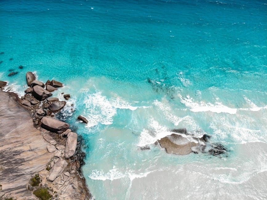
Water Sports & Diving
Western Australia’s extensive coastline provides world-class opportunities for water sports and diving, thoroughly covered in travel guides. Ningaloo Reef is a highlight, famed for whale shark encounters and vibrant marine life, with guides detailing tour operators and responsible interaction practices;
Explore the Coral Coast’s pristine beaches for surfing, windsurfing, and kitesurfing. Perth’s Swan River offers calmer waters for kayaking and paddleboarding. Dive sites cater to all levels, from beginners to experienced divers, showcasing shipwrecks and coral gardens. Guides provide safety advice, equipment recommendations, and information on local conditions for an unforgettable aquatic experience;
Indigenous Culture & History
Western Australia boasts a rich Aboriginal heritage, deeply explored within travel guidebooks. Discover ancient stories and traditions through visits to heritage sites, with guides providing respectful insights into cultural significance. Explore art and cultural centers showcasing traditional and contemporary works, learning about Dreamtime stories and artistic practices.
Guides highlight opportunities to engage with Indigenous-led tours, offering authentic experiences and supporting local communities. Learn about the impact of colonization and the ongoing efforts towards reconciliation. These resources emphasize responsible tourism, encouraging visitors to appreciate and respect the enduring culture of Western Australia’s First Peoples.
Exploring Aboriginal Heritage Sites
Travel guidebooks detail numerous sites across Western Australia offering profound connections to Aboriginal history. Discover ancient rock art galleries, sacred landscapes, and ceremonial grounds, each holding significant cultural meaning. Guides emphasize respectful visitation, encouraging learning about the stories and traditions associated with these places.
Explore sites like the Burrup Peninsula (Murujuga National Park) with its extensive rock engravings, and learn about the deep spiritual connection Aboriginal people have with the land. Responsible tourism is key; guides advocate for supporting Indigenous-led tours and respecting cultural protocols when visiting these important heritage locations.
Art & Cultural Centers
Western Australia travel guides highlight vibrant art centers showcasing contemporary and traditional Aboriginal art. Discover galleries featuring paintings, sculptures, and crafts, offering insights into Dreamtime stories and cultural practices. These centers often provide opportunities to meet artists and learn about their creative processes.
Explore the Fremantle Arts Centre, known for its exhibitions of Indigenous art, and various regional galleries promoting local talent. Guides emphasize the importance of purchasing art directly from artists or reputable centers that support Indigenous communities, contributing to cultural preservation and economic empowerment.
Wildlife Encounters
Western Australia travel guide books detail incredible wildlife experiences, from observing unique Australian animals in their natural habitats to exploring protected national parks. Discover opportunities to encounter kangaroos, koalas, and diverse bird species. Guides emphasize responsible wildlife tourism, advocating for minimal disturbance and adherence to park regulations.
Explore national parks dedicated to conservation, offering guided tours and educational programs. Learn about the region’s unique biodiversity and the efforts to protect endangered species. These guides highlight ethical animal interactions, promoting respect for wildlife and their ecosystems, ensuring a memorable and sustainable experience.
Unique Australian Animals
Western Australia travel guide books showcase the state’s extraordinary fauna, including iconic species found nowhere else. Discover the quokka, famed for its smiling expression, and the elusive numbat, a striped marsupial. Guides detail prime locations for spotting these creatures, emphasizing responsible viewing practices to minimize disturbance.
Learn about the diverse range of reptiles, birds, and marine life inhabiting Western Australia’s varied landscapes. These resources provide insights into animal behavior, habitats, and conservation status, fostering appreciation for the region’s biodiversity. Ethical wildlife encounters are prioritized, promoting respectful interactions and supporting conservation efforts.
National Parks & Conservation
Western Australia travel guide books extensively cover the state’s vast network of national parks, highlighting their unique ecosystems and conservation importance. Explore detailed maps and visitor information for parks like El Questro Wilderness Park and Purnululu (Bungle Bungle) National Park, learning about access, facilities, and responsible travel guidelines.
These guides emphasize the significance of preserving Western Australia’s natural heritage, detailing ongoing conservation initiatives and opportunities for sustainable tourism. Discover how to minimize your environmental impact while enjoying the state’s stunning landscapes, supporting local efforts to protect its biodiversity for future generations.
Practical Information
Travel guides provide essential details on accommodation, dining, and logistical planning for a smooth Western Australian adventure, ensuring a stress-free experience.
Accommodation Options
Western Australia boasts a diverse range of lodging choices to suit every traveler and budget. From luxurious hotels and resorts in Perth and Margaret River, offering world-class amenities and stunning views, to charming bed and breakfasts nestled in coastal towns, there’s something for everyone. Backpackers will find numerous hostels providing affordable and social accommodation.
For a unique experience, consider staying in remote wilderness lodges or eco-retreats, particularly in the Kimberley region. Camping is also a popular option, with well-maintained campgrounds available in national parks and along the coast. Booking in advance is highly recommended, especially during peak season, to secure your preferred accommodation. Travel guides often feature curated lists and recommendations to help you find the perfect place to stay throughout your Western Australian journey.
Food & Drink
Western Australia’s culinary scene is a delightful fusion of fresh, local produce and diverse influences. The Margaret River region is renowned for its world-class wineries, producing exceptional Cabernet Sauvignon and Chardonnay. Sample gourmet cheeses, olive oils, and chocolate alongside your wine tasting. Perth offers a vibrant dining experience, with restaurants serving everything from modern Australian cuisine to Asian fusion.
Don’t miss the opportunity to savor fresh seafood along the coast, including Western Rock Lobster and locally caught fish. Indigenous ingredients are increasingly featured in menus, offering a unique taste of the land. Enjoy craft beers at local breweries and explore the growing coffee culture. Travel guides often highlight regional specialties and recommended eateries.